
As a road safety engineer, I often say that high-quality automatic bollards are masterpieces of “invisible engineering.” To the average person, they are nothing more than heavy metal cylinders: capable of rising from the ground like magic to block vehicles, yet able to disappear completely beneath the road surface to restore traffic flow.
However, beneath its surface lies a complex and highly synchronized system, specifically designed to withstand harsh weather, handle high-frequency operation, and endure potentially devastating vehicle impacts. Below, we’ll provide an in-depth analysis of how an automatic rising bollard system works, from its core structural components to the “brain” of its drive mechanism.
Core Components: An Analysis of the Automatic Bollard’s Structure
An automatic rising bollard system primarily consists of two major parts: the bollard body visible above ground and the structural foundation buried underground.
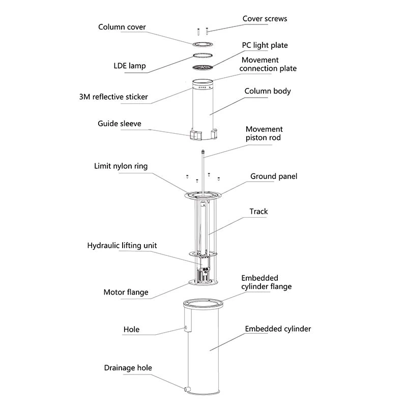
Bollard Body (Main Body of the Rising Bollard): This is the visible, movable column, typically manufactured from high-strength carbon steel or 304/316-grade stainless steel. Its wall thickness varies: standard commercial traffic management applications typically use 6 millimeters, while anti-terrorism-grade roadblocks with crash-resistant certification can exceed 20 millimeters.
Foundation Sleeve (Outer Cylinder): This is a heavy-duty steel casing permanently embedded in a reinforced concrete foundation. It guides the column’s vertical movement, absorbs the majority of the kinetic energy during an impact, and safely transfers the force to the ground.
Drive Mechanism: Typically located inside the column and connected to an external control box, this mechanism provides the mechanical power required to raise and lower the heavy steel column.
Drive Mechanism: Lifting Principle
Automatic rising bollards primarily rely on three different engineering drive systems to operate. The specific choice depends on the installation environment and the expected frequency of use.
1. Hydraulic System (High-Power Drive Type)
Hydraulic automatic bollards are the industry standard for areas requiring high security levels and high vehicle traffic. This system uses an electric motor to pump pressurized hydraulic fluid into the piston cylinder.
Operating Principle: When a “raise” command is issued, the pump forces fluid into the bottom of the piston, causing the bollard to rise; to lower the bollard, a valve opens to reverse the flow of fluid.
Engineering Advantages: Hydraulic systems offer exceptional lifting force, smooth operation, and an exceptionally long service life. High-security models are typically equipped with an “Emergency Fast Rise” (EFR) system, which utilizes a pre-pressurized fluid accumulator to rapidly raise the bollard within 1.5 seconds in the event of a security breach.
2. Electromechanical Systems (Precision-Drive Type)
Electromechanical rising bollards are becoming increasingly popular in residential areas and light commercial settings (i.e., areas with high cleanliness requirements).
Operating Principle: This system uses an electric motor connected to a heavy-duty mechanical lead screw or ball screw. The rotation of the motor drives the screw, which in turn moves the nut attached to the rising bollard up or down via mechanical transmission.
Engineering Advantages: Since no hydraulic fluid is used, this system completely eliminates the risk of fluid leakage into the environment. Additionally, these systems perform exceptionally well in regions with stable and moderate climates and provide precise positioning control.
3. Pneumatic System (Clean and High-Speed Type)
Pneumatic systems rely on compressed air rather than hydraulic fluid or mechanical gears for propulsion.
Principle of Operation: A central air compressor pumps compressed air through underground piping into the bollard housing, thereby raising the bollard.
Engineering Advantages: Pneumatic systems operate extremely quickly and maintain high reliability even in sub-zero temperatures (where hydraulic oil may thicken). However, this system requires dedicated and well-maintained air compressor infrastructure nearby.
Control Core: Integration and Safety
For automatic rising bollards to operate safely, they rely on the coordinated work of an integrated control unit (i.e., a PLC, or programmable logic controller) and a series of safety sensors. When a user triggers an access command—whether via a mobile app, remote control, RFID access card, or license plate recognition camera—the central control panel verifies the signal and activates the drive mechanism. However, before the rising bollard moves in any direction, the system first checks its safety induction loop.
Function of the Sensing Loop: Magnetic induction coils are embedded beneath the asphalt pavement in front of and behind the bollard. These coils detect the mass of metal vehicles passing overhead. If a vehicle is detected directly above a lowered bollard, the PLC blocks any “raise” command, thereby preventing the heavy steel bollard from accidentally rising and striking the vehicle’s undercarriage.
In addition, most engineering specifications require an integrated drainage system at the bottom of the foundation housing. Since these systems are installed underground, heavy rain or road-cleaning operations can easily cause mechanical components to become submerged. By installing gravel drainage pits or automatic sump pumps, the internal chamber can be kept completely dry, thereby protecting electronic components and mechanical transmission mechanisms from corrosion.
With their robust metal construction, powerful fluid or mechanical drive systems, and integrated smart sensor technology, modern automatic rising bollards have become reliable and discreet guardians in the field of modern perimeter security.